Cement printing is a new field within 3D printing. In a previous blog I discussed how I modified the large volume extruder (LVE) to fit onto a Lulzbot Taz 5 3d printer.
For this blog I’ll detail how I assemble the modified LVE core. The LVE was 3D printed with Colorfabb PETG and Colorfabb PLA/PHA. The original LVE was designed by Thomas Hunton, and his instructions can be found here.
Mount to the Core
To adapt the LVE from the original printerbot setup to Luzbot, I used tinekrCAD to make an adaptive mounting plate. I also added some reinfrocment to the LVE core and made it easier to change out the screw rod.

In the core file, I put a set of holes through both sides to make it easier to run your Allen keys through to the mounting plate.
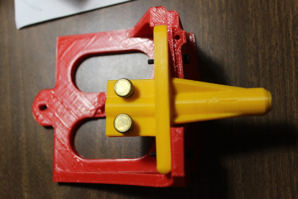
Cement Printer Syringe Plunger
The main part of this assembly is the syringe plunger assembly that connects the motor to the filled syringe pump.
After printing the nut shuttle and plunger, make sure to test fit the plunger and shuttle together. I found that the plunger was difficult to 3d print, so the fit into the shuttle was impossible. I had to take sandpaper and fine files to the nut shuttle and plunger to get them to fit. Next time I’d print the nut shuttle at 0.2 mm or finer to make it smoother.
Putting the M8-1.25 nut into the shuttle was also a tight fit. Sense this nut is the one that is turned to move the shuttle back and forth, I wanted this to be a snug captive fit.
Rather than try to deal with more sanding, I remembered a method for fitting aircraft propellers to propeller shafts.
In that method, you place the propeller shaft on dry ice to get it to contract, then shove into the propeller and it will expand to a tight fit when warm.
For this I put the plastic nut shuttle in hot water to get it to expand, and the nut on ice to shrink it. With this method, it was possible to get the nut to fit into the shuttle snugly.
Using three(3) M3-10 socket cap bolts and M3 nuts, I secured the back plate on.
Rod Assembly
For the rod assembly, I used four (4) M8-1.25 nuts and two (2) zz809 bearings (think cheap and scrounge them from some broken fidget spinners).
Placing the rod and shuttle in place in the core, I drooped the rod assembly in place and adjusted the nuts to space the bearings correctly at the back of the core.
In the original core file, there was an overhang that you would have to thread the whole rod through to change out the plunger. I modified the core file with a cut out because I knew I would have to adjust the whole rod assembly, and I’m worried in the future I may have to quickly change out the rod assembly if the cement filled syringe gets clogged.
Motor
In the video Hunton uses M3 x 16 caps screws and M3 nuts, but I found those to shallow to go through the small gear. I uses M3 x 20’s instead to attach the gear to the motor.
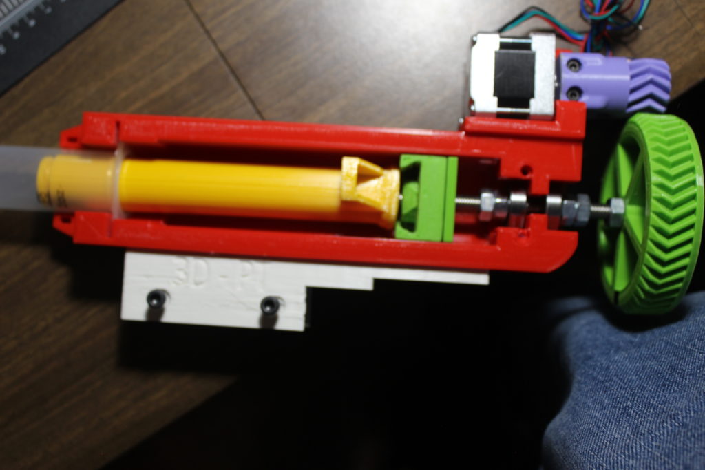
The M3 x 16 bolts were used to mount the motor to the core.
Large Gear
The large gear also had a tight fit onto the rod, and I ran out of M8 x 1.25 nuts. It turns out that I could screw the gear straight onto the rod, and use my last M8-1.25 to secure it. It should not have an issue unscrewing from the main shaft.
Cement Printer Tool Head
While I was shopping the local big box hardware store for metric hardware, I also found some brass knurled thumbscrews that I thought would come in handy. I anticipate that I’ll have to make quick changes to the nozzle and tool head. As I was putting the tool head together I saw where I could improve it and add the thumbscrews for a quick change. In the future I hope to use this quick change system for improvements and cleaning.